
 Enquiry:hkmarketing@epc.com.hk
Description
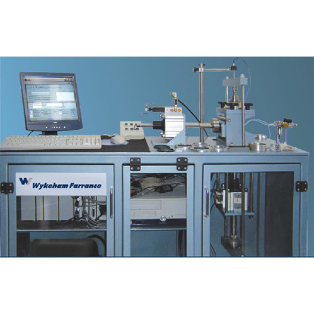
The cyclic simple shear apparatus is generally used for research in the dynamic field of soil behaviour, and can quite easily simulate many different field loading conditions, for example:
- Stability under seismic events on submerged slopes of the continental shelf characterised by layered clays
- Degradation of shear stress in cohesive soils under cyclic loading
- Evaluation of the liquefaction parameters of non-cohesive soils under cyclic loading
The cyclic simple shear is a plane strain device. The shear strain is induced by horizontal movement at the bottom of the sample relative to the top. The diameter of the sample remains constant, therefore any change in volume can only be as a result of vertical movement of the top platen.
The system is designed to allow a sample to be consolidated and then sheared under constant volume conditions (simulating an undrained shear of a saturated specimen).
Sample
The standard sample is 70 mm diameter. The test can also be performed on 50 mm diameter samples using the conversion kit 31-WF7500/1.
The sample is positioned on a pedestal, with a top cap the same as used for triaxial testing, and is supported laterally by a rubber membrane secured with O-rings. To maintain a constant diameter throughout the test the sample is restrained by a series of slip rings.
Shear stage
During shearing the rings slide across each other as shown in picture 3 above, while keeping the diameter constant. The vertical height of the sample is maintained constant by the vertical actuator under closed-loop control with feedback from the vertical displacement transducer. The change in vertical stress required to achieve constant height is assumed to be equal to the change in pore pressure.
Below is a general description of the main system components:
Base system
The system consists of a simple shear load frame fitted with an air receiver with servo-valves for controlling vertical and horizontal load/displacement. It incorporates a control and data acquisition system as described below, with two 5 kN actuators. The system is housed within a cabinet. The horizontal and vertical actuators are fixed to the frame, which supplies the reaction to the forces applied. Each actuator has an internal displacement transducer, which relays the actuator piston position back to the computer. This is very important when setting up a sample; it allows you to set enough travel for the test duration. The sample is set up in the machine, which has a rigidly fixed top half and a moving bottom half. The top half houses the 50mm diameter vertical ram. This is housed in a linear bearing to allow vertical movement and prevent horizontal movement. The bottom half is mounted on roller bearings as in a standard shear box.
Integrated Multi-Axis Control System
The IMACS is a compact self-contained unit that provides all critical control, timing and data acquisition functions for the test and the transducers. It is linked to a personal computer through a USB communications link.
The data acquisition module has 13 normalised (±10 V range) transducer input channels. These channels are digitised by accurate, high speed 20 bit (A/D) converters for data analysis and presentation. The control module has two channels for feedback control. One is dedicated to the vertical actuator for load/displacement, the second is for the horizontal actuator for load/displacement. The feedback control module and the data acquisition module have their own dedicated high speed USB 10 Mbit/s or RS232 interface. This allows uninterrupted, simultaneous communication, giving increased speed of cooperation and flexibility.
Supervised by the PC, the IMACS automatically controls the operation of loading
for individual types of test. The IMACS directly controls the servo-valve to apply the requested loading rate or waveform. While the specimen is being subjected to loading forces, the IMACS captures data from the transducers and transfers these, via the USB or RS232 link, to the PC for processing, display and storage.
Load cells
These two 5 kN load cells are fitted in-line with the horizontal and vertical actuators.
The load cells are fitted with a calibration module, allowing the transducers to be changed or moved within the data acquisition system without the need to recalibrate them. Accurate to 1 N.
Displacement transducer
This ± 15 mm displacement transducer is built into the actuator. It measures the actuator piston position and can also be used as the control transducer for the cyclic strain test.
Vertical displacement transducer
This transducer is calibrated over ± 2.5 mm for controlling the sample height. Accurate to 1 μm.
In-line signal conditioning
This normalises all the transducer outputs, allowing transducers to be moved from channel to channel without having to recalibrate.
The system includes the following:
- Cyclic simple shear machine with horizontal and vertical actuators 5 kN capacity
- Accessories for sample preparation
- Force and displacement transducers
- Control system and data acquisition
- Software and PC
For a complete test configuration please contact our team of specialist.