
 Enquiry:hkmarketing@epc.com.hk
Experimental content
- To convert a head measurement using a manometer to an equivalent pressure reading
- To demonstrate the use of a static pressure reading to determine tunnel air velocity
- To convert head and pressure readings to alternative engineering units
- To demonstrate the difference between Static pressure, Dynamic pressure and Total pressure and how Dynamic pressure can be used to determine air velocity
- To show how velocity varies in the test section because of the velocity profile
- To investigate the variation in Static Head resulting from a change in cross-sectional area
- To investigate the Bernoulli equation
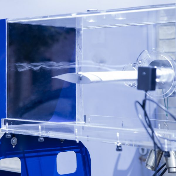
- The visualisation of flow around a bluff body at different velocities
- The measurement of pressure distribution around a circular cylinder at different velocities
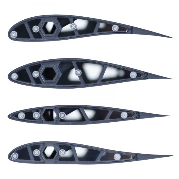
- Comparison of drag for shapes of equal equatorial diameter
- Visualisation of flow around different body shapes
- Measurement of the wake profile behind different shapes
- To investigate the pressure distribution around a symmetrical aerofoil at different angles
- To investigate the pressure distribution across the wake behind the wing
- To measure the depth of the boundary layer on smooth and rough flat plates
- To evaluate models or instruments of the students own design and/or manufacture
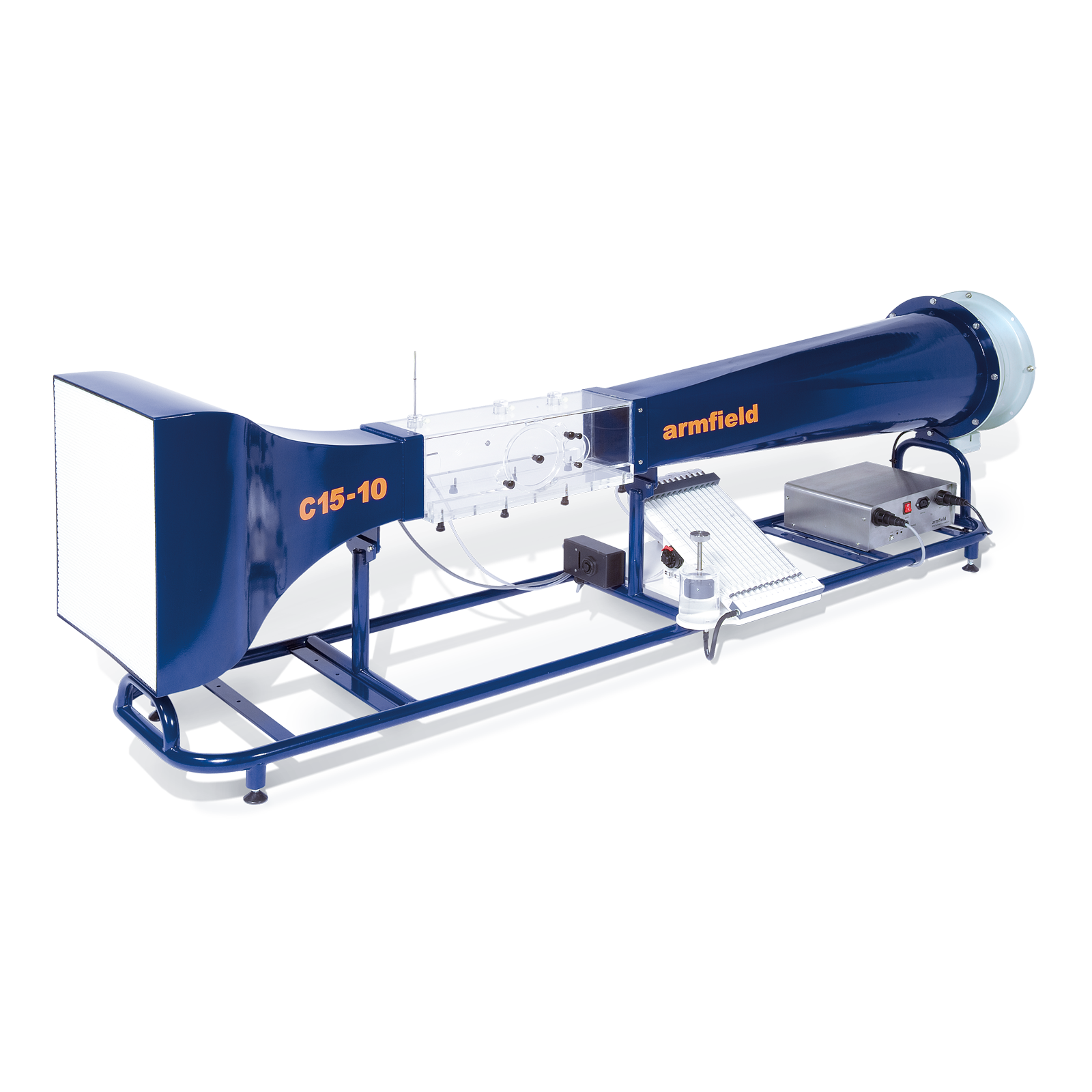
The C15-10 is a computer controlled compact wind tunnel designed for benchtop operation. Air is drawn through the working section by a variable speed fan at the discharge end of the tunnel providing up to 34m/s air velocity.
A honeycomb flow straightener is incorporated at the inlet, and a 9:4:1 contraction ratio which ensures a uniform airflow through the working section.
The working section is fabricated from clear acrylic to provide optimum visibility of the models and appropriate model connection points are included in the side wall and roof of the working section to provide ease of use.
The wind tunnel is supplied as standard with an in-depth software interface providing control of the fan speed and additionally display important parameters such as static pressure and air velocity.
The Armfield C15-10 can be optionally supplied with two variants of manometry banks, a 13 tube water manometer used to simultaneously display differential pressure or a sixteen channel electronic manometer allowing direct integration into the supplied software.
The wind tunnel can be supplied with a range of optional accessories including drag bodies, lift bodies, pressure distribution, boundary layers studies and measuring instruments.
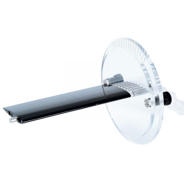
The optional models are mounted through a circular hatch using quick release clamps (120mm diameter). The placement of the optional models has been designed to minimise the disturbance to air flow and reduction in flow rate, whilst incorporating an angular scale allowing the model to be manually rotated to known angles.
The working section incorporates an innovative technique for flow visualisation around any of the optional models avoiding the need for either smoke or dry ice. A lightweight twine follows the flow contour around the model and shows if and where boundary layer separation (breakaway) occurs.