
 Enquiry:hkmarketing@epc.com.hk
Description
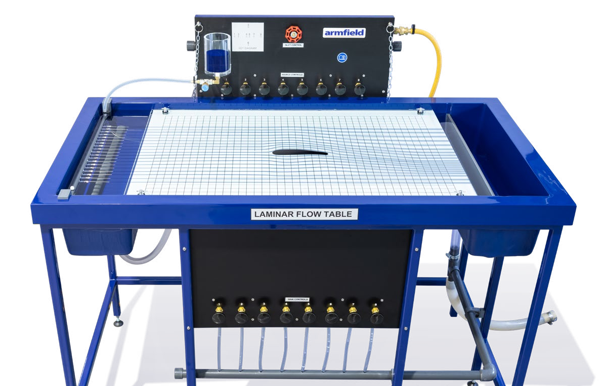
The C10 Laminar Flow Table is an improved version of the classical Hele-Shaw apparatus with the addition of sinks and sources. It consists of two closely spaced sheets of laminated glass, arranged horizontally on a glass fibre moulding.
An inlet tank and discharge tank are incorporated in the moulding, which is supported on a floor-standing, metal frame. Three adjustable feet enable rapid levelling of the flow table.
Eight miniature tappings, which may be used as sinks or sources, are arranged about the centre line of the lower glass plate in a cruciform configuration. A doublet (a sink and source in close proximity) is located at the centre of the pattern. A system of pipes, valves and manifolds enables any combination of the sinks and sources to be used.
A row of control valves mounted above the flow table is used to adjust the flow through each individual source. A row of sink control valves is used to adjust the flow through each individual sink. A row of hypodermic needles attached to a manifold is positioned between the glass plates at the inlet edge.
To visualise the flow of water between the glass plates, dye is injected through the equally spaced needles. The position of each streamline is clearly indicated by the dye, which is supplied from a reservoir fitted with a flow control valve. A black graticule on a white background is printed on the underside of the lower glass plate to aid visualisation of the streamlines.
The patterns created by the potential flow may be recorded by tracing on the top glass sheet or by photography if required. A diffuser in the inlet tank and an adjustable weir plate in the discharge tank help to promote a uniform flow of water. Valves are incorporated in the base of these tanks to aid draining. The flow of water is controlled by an inlet flow control valve. A pressure regulator reduces the mains water pressure and helps to minimise variations in flow.
The top glass plate may be raised at the front edge and retained in this position to enable models to be placed in the working section. A set of models are supplied for basic flow studies.
These models are manufactured from plastic sheet and are trapped in the required position when the top glass plate is lowered. Alternative models can be fabricated from any convenient material and used to investigate the associated flow patterns.
Two-dimensional laminar flow is created between the two glass plates by the combination of low fluid velocity and the narrow gap between the plates. The resulting flow is free from turbulence and gives a close approximation to the behaviour of an ideal fluid.
Since the flow is controlled by potential, the flow table can be used to model any physical system that obeys Laplace’s Law. For example, two- dimensional steady heat flow through a conductor of varying cross section can be simulated. In this instance the heat flow is represented by the flow of water and the temperature difference in the system is represented by the fluid pressure potential.
Similarly, the sinks and sources may be used in combination with the flow of water between the plates to simulate a variety of flow situations. For example, the patterns of flow in the vicinity of wells, which draw water from underground supplies (aquifers) may be represented using one or more of the tappings as sinks. The effect of recharging the underground supply may be represented by utilising one or more of the tappings as sources.
Technical specifications
Working section
Width inside moulding
606mm
Length of glass plates
892mm
Distance between glass plates
3.2mm
Sinks/sources
Eight tappings in seven positions
Dye injectors
19 hypodermic needles
Models supplied
2x canal banks
2x rectangles
3x cylinders
1x aerofoil
3g of blue dye powder also supplied
(makes 1l of dye solution when added to water)
|
Overall dimensions |
|
|
Dimensions |
|
|
Length |
1.32m |
|
Width |
0.78m |
|
Height |
1.15m |
|
Packed and crated shipping specifications |
|
|
Net weight |
2.0m3 |
|
Gross weight |
220Kg |